


how i'm building a solar-powered charger for backpacking
part 1 of the series: why and how I'm doing it! (it's giving science fair project)

TLDR: I’m building a solar-powered battery pack to charge my electronic devices during a weeklong backpacking trip in Banff! I’ve validated that the system works by connecting my solar panels to a controller, a sensor, an Arduino, OLED display, and the battery pack via a breadboard. This week, I’ll be soldering permanent connections and mounting everything in a weather-proofed junction box! More to come.
At the retreat I attended last week, I spent many days working next to a guy named Rahim. He was building an ATM connected to a raspberry pi. Why don’t you try building something with hardware? he’d asked me during a break. There’s no better way to get hands-on practice.
I didn’t really have a good answer, other than that I was intimidated. The people out there “just building things” are cobbling together nuclear fusors in their dorm rooms or launching weather balloons into the stratosphere. A team at the retreat a week before me even built a solar powered data center that provided free compute (shoutout
+ for being so friendly and inspiring me by doing amazing work!) It was crazy fast and super cool.I’d been building a scroll-based website on the energy stack, with deep dives on generation, interconnection, transmission, distribution, and everything in between including storage, DERs, etc. I’m about 75% of the way done. But Rahim’s comments struck me with a newfound inspiration. Hands-on learning does hit different.
Lowering the stakes definitely helps. LLM assistants also really help. Everything sort of becomes stupid easy with this mindset - even hardware feels accessible. There’s really no good excuse for why one shouldn’t just try to build anything. And there’s no better way to start than by just doing.
I’m backpacking in Banff starting on June 30. So I decided to give myself two weeks to build something small that I could use on that trip, just for fun.
Solar-powered battery packs to charge your electrical devices with do exist, and they’re not expensive. But according to reviews, they’re sort of bummy and should be fully charged before you use them which feels a bit like cheating.
Given my zero electrical engineering experience, I thought this would be an easy place to start. And it’s way more fun to make your own than to buy it off Amazon (I say, having bought literally all my parts off Amazon).
I’m still working through the kinks, but here’s some documentation on my first full day working on this in my spare time!
Day 0: Gather materials
The first step was to gather all the materials. Pretty straight forward, but I had nothing. I wasn’t going to build a solar panel or a battery from scratch so I started with:
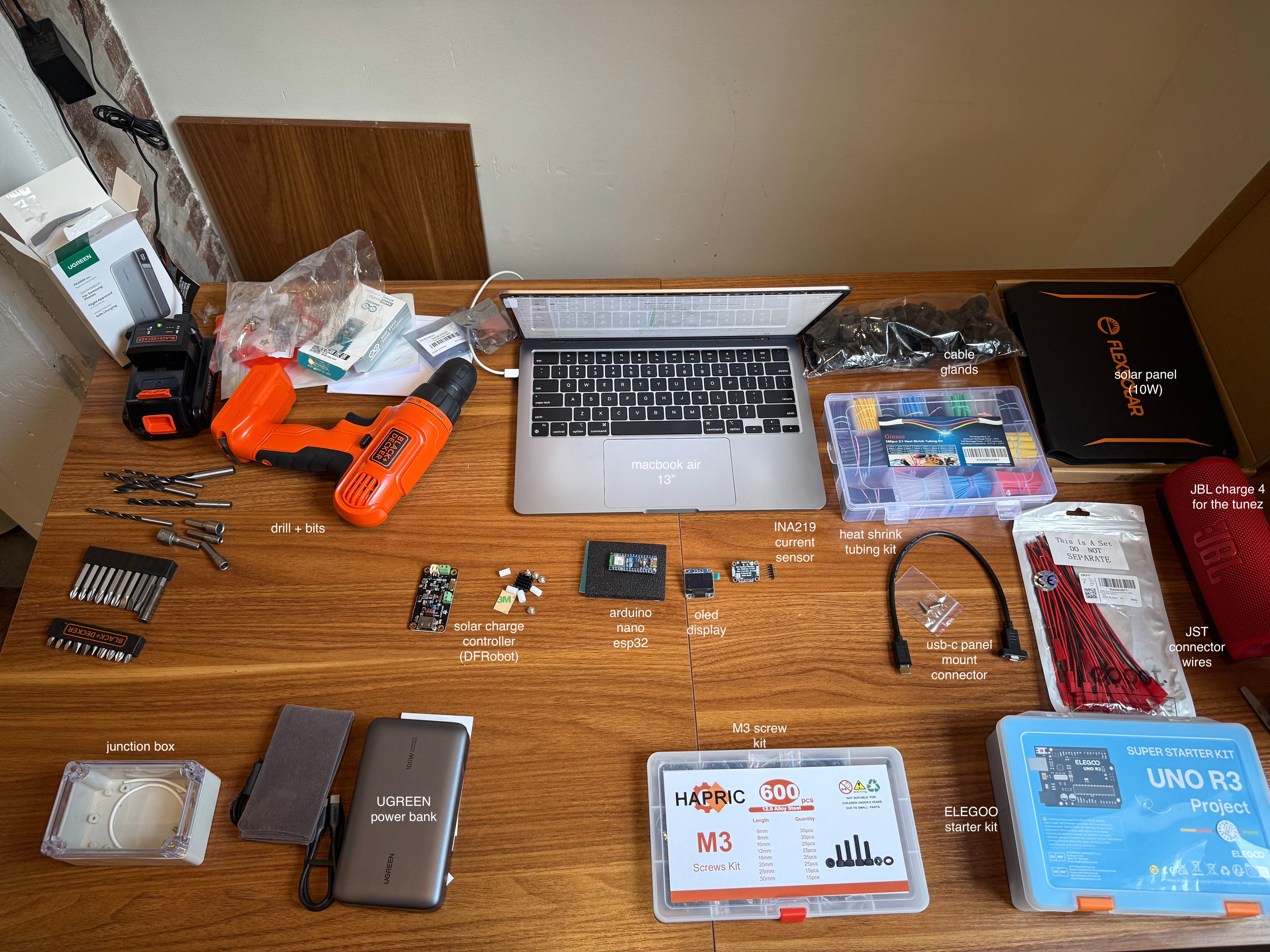
a 10W / 5V solar panel from Flexsolar (just panels)
a power bank (I started with the UGreen 20,000AU but it was bulky and overkill so I switched)
a solar controller from DFRobot (to make sure the voltage is consistent between the solar panels and the battery)
a INA219 current sensor to measure how much solar power is going to the battery
an arduino nano ESP32 for coding my display
the OLED display
a junction box (the one pictured was too small so I bought a bigger one)
an ELEGOO starter kit that included breadboard + dupont cables
classic rock, for the vibes
It took all of these items ~3 days to arrive, and cost me about $260.
Day 1: Begin Assembly
One thing about building things from (almost) scratch is that it really forces you to think from first principles. And one thing about Claude - Sonnet 4 specifically - (my assistant of choice) is that it can be dummy. I am still getting used to prompting it in an effective way so the dummy is largely on me. But it was telling me to start by drilling holes into my junction box to fit wires through it that weren’t connected to anything yet. That seemed like not the correct order of operations.
We then debated how I was going to configure everything at a high level. This ended up being stupid too, because you can’t fully know exactly what you need or what you’re going to do until you start. So just start.
That said, here’s the flow of power:
solar panel → solar controller → current sensor → battery pack
in parallel, this flow happens to monitor and display the current and power levels:
battery pack → Arduino ESP32 → OLED display → current sensor
So here are the steps I took:
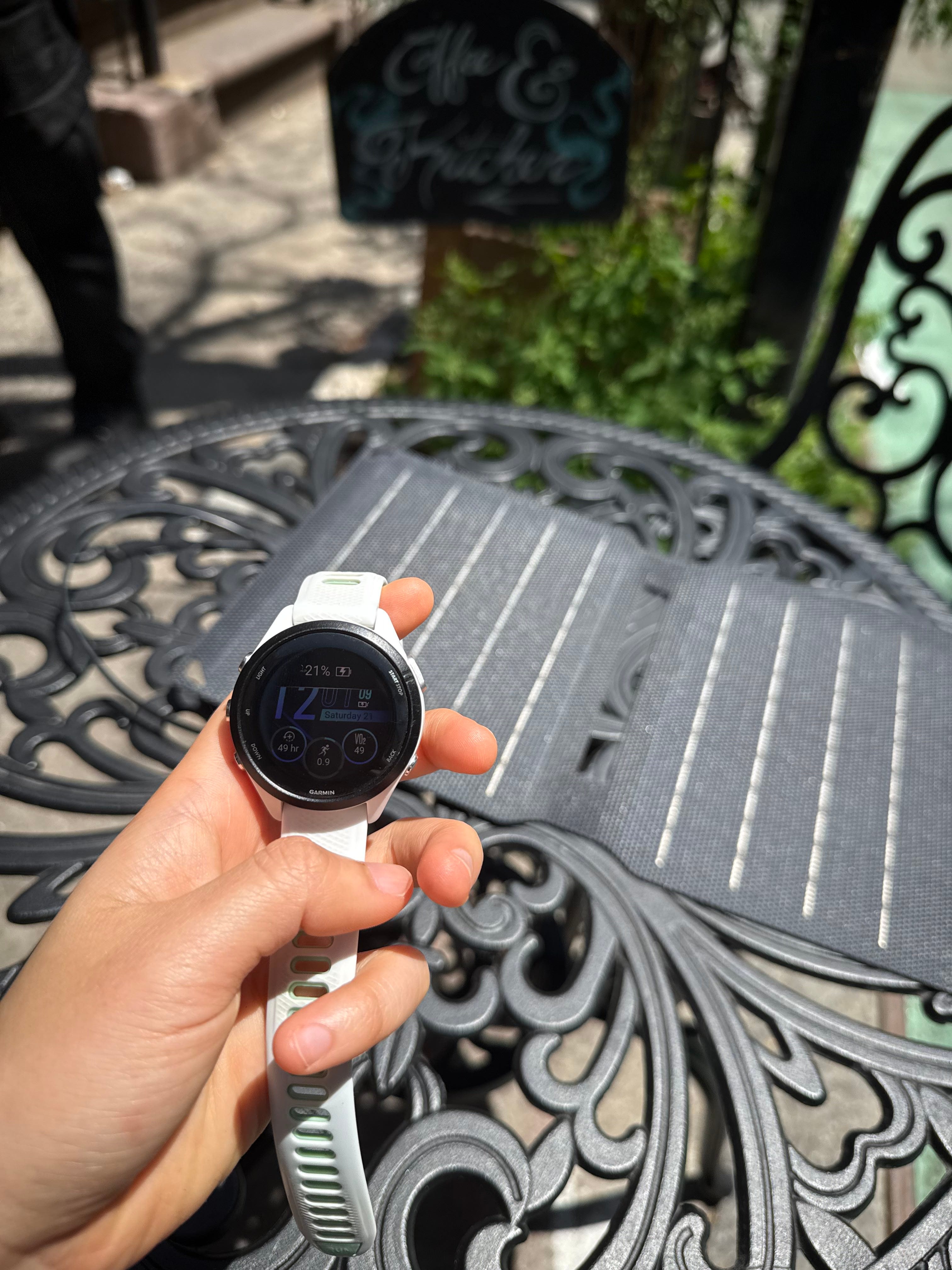
testing my solar panel
The solar panel works by taking in sunlight and converting it to electric current. It has a USB-A output port. This was confirmed to work when I took it out on a sunny day to charge my Garmin.
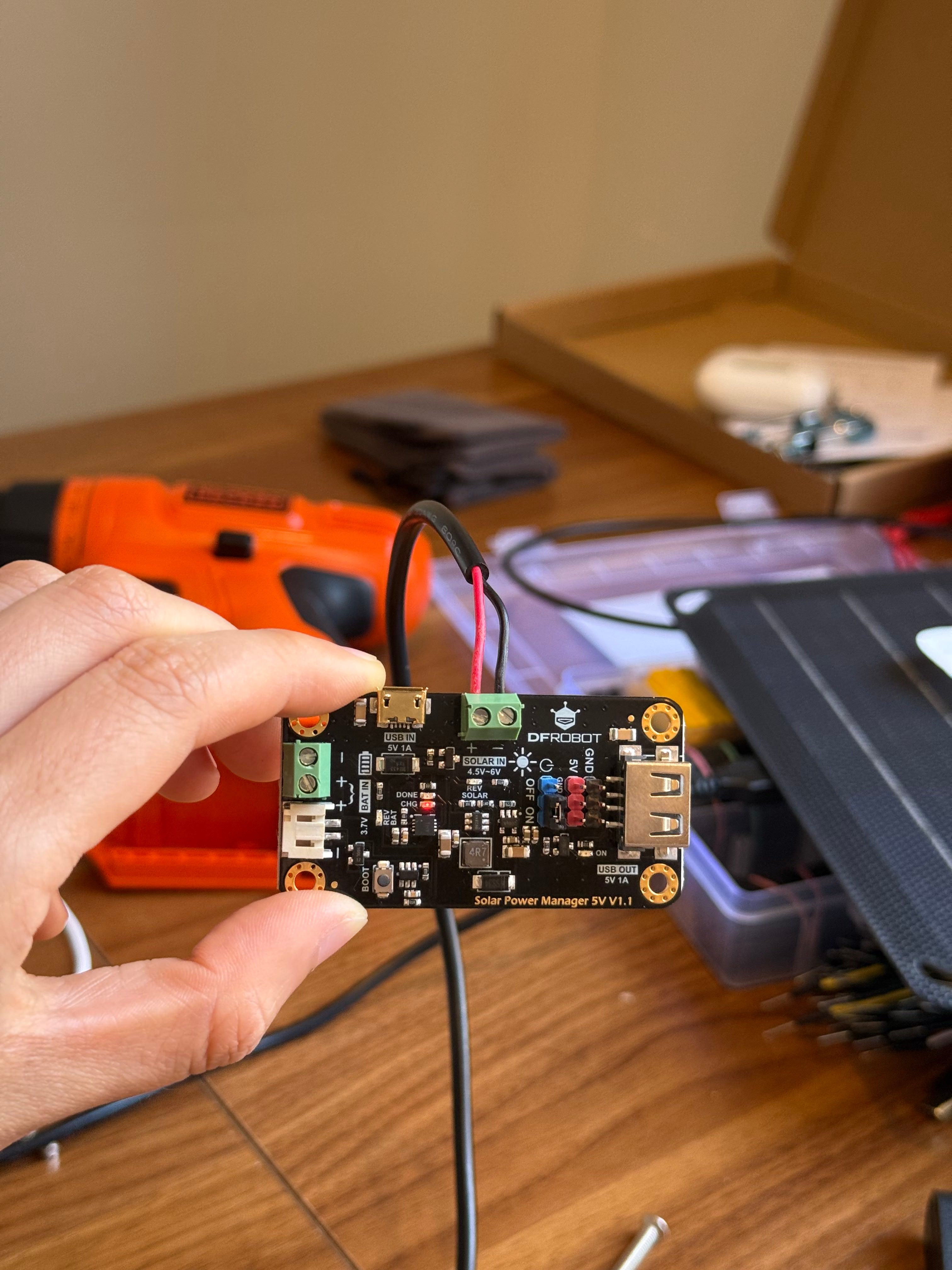
connecting my solar panel to the controller
The purpose of having a controller is primarily for voltage regulation. This is necessary because solar panels often output variable voltage, depending on how sunny it is. My 5V USB power controller converts and stabilizes the voltage coming from the solar panel to exactly 5V. As such, it prevents overcurrent that could damage my power bank. It’s not high risk, but feels right to include on principle.
The solar panel connects to DFRobot controller via a USB-A cord that has the red + black (positive + negative) copper wires exposed and stripped so they can be plugged into green block terminal on controller. This is what copper wires look like when they’re stripped and then soldered at the end:
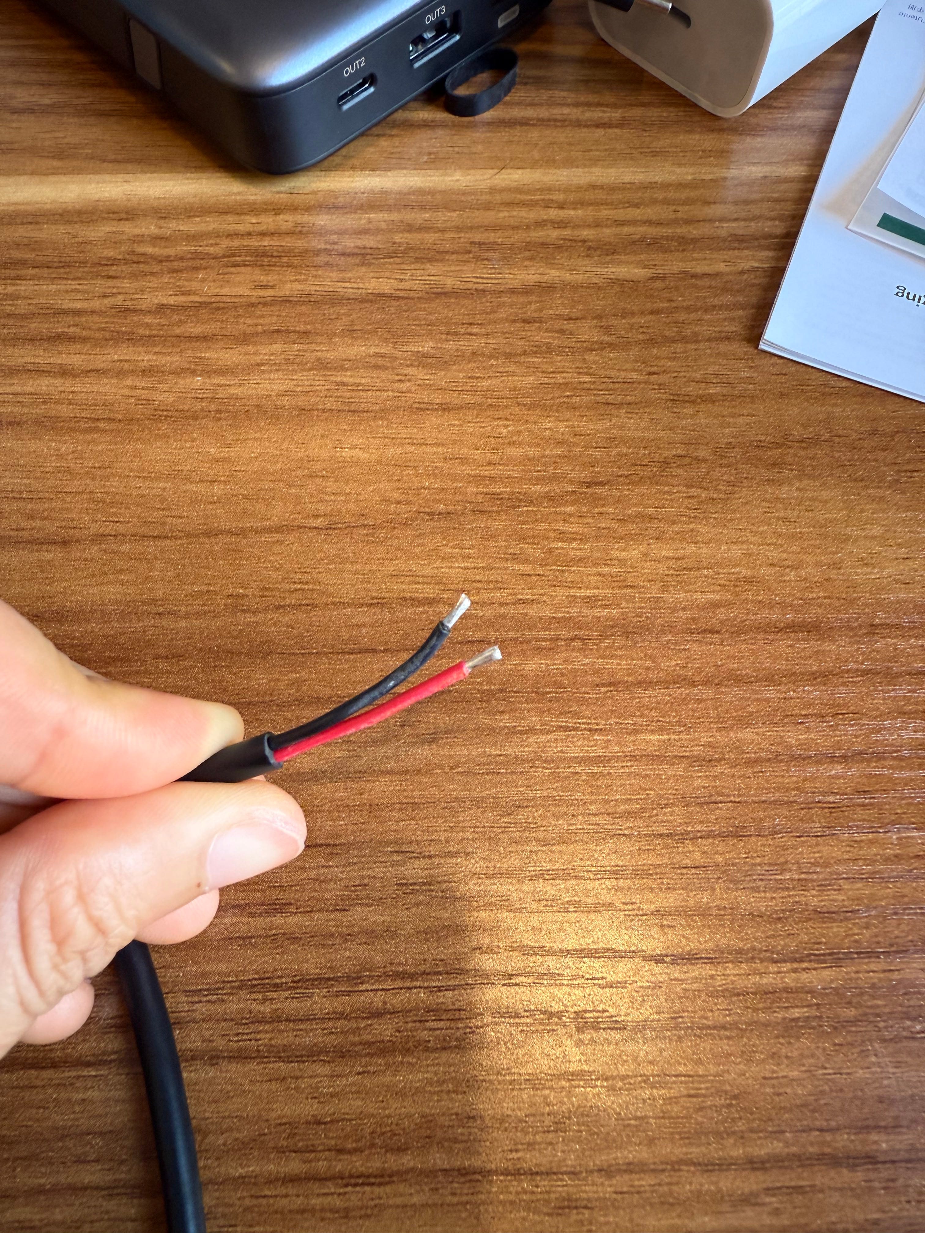
The red goes into the positive end of the terminal, and the black into the negative. You do this by using a mini screwdriver to loosen the terminal, stick them in, and then tighten the terminal again. They should be firmly inserted when you gently tug. When I connected this cord to my solar panel, it responded with a constant red LED signal next to CHG, that supposedly means its working.
adding the current sensor to the flow
The current sensor’s purpose is to detect and measure the flow of electrical current in a circuit. Essentially, I need it so I can track and display how much power is flowing through my system on the OLED screen. This is the current sensor I’m using:
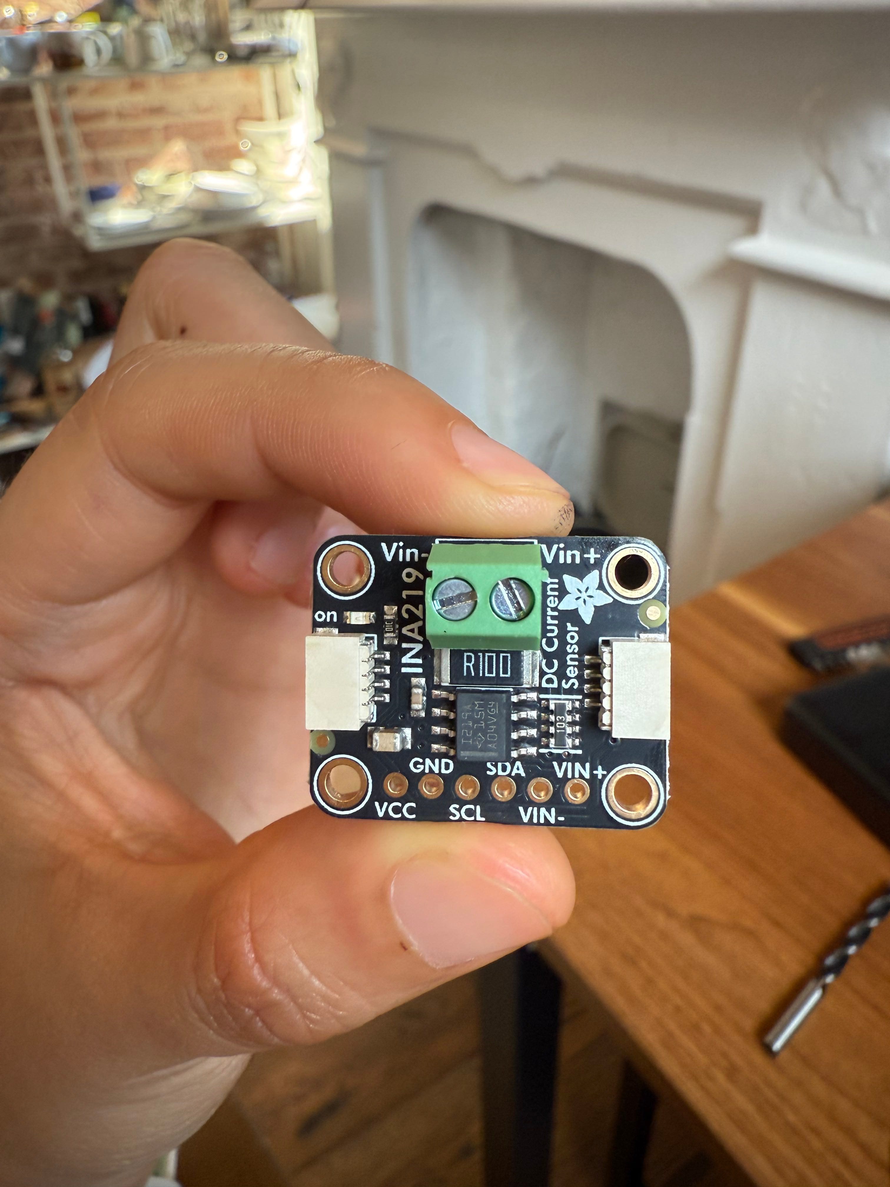
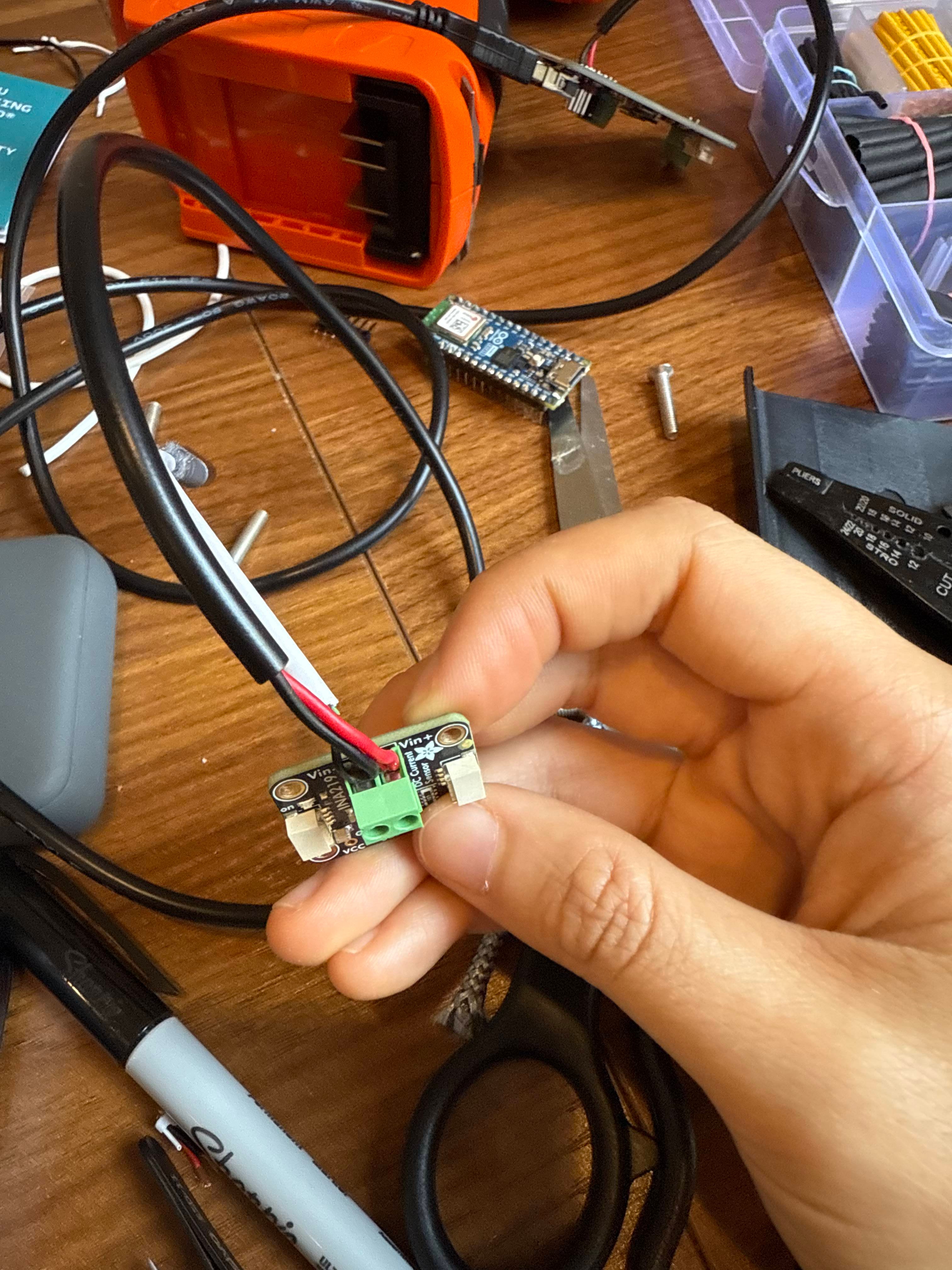
Just like the controller, it has green block terminal (+ and -) and it also has connections for Dupont cables at the bottom. To connect them to the controller (so it can measure how much current is coming from the panel through the controller), I used a USB-A head that was attached to my controller’s output port, and then cut that cable, stripped the red and black wires, and plugged them into the terminal. I had to do the same for another cable that had a USB-C head, which would connect to my power bank so it could receive the solar charge. Thus, I ended up with 4 wires connected to my sensor:
adding the Arduino + OLED display to monitor
This was my first time using an Arduino! For those who are unfamiliar, it’s an open source hardware + software platform that people often use to create electronic projects, essentially a small computer, that can read inputs (like how much current is flowing) and control outputs (like displaying data on my OLED screen).
I’m using the Arduino Nano ESP32, which is the first ever Arduino board based on a ESP32 microcontroller from Espressif which can use Wifi/Bluetooth. Here’s a closer look at the Arduino, my oled display, the sensor, and my controller:
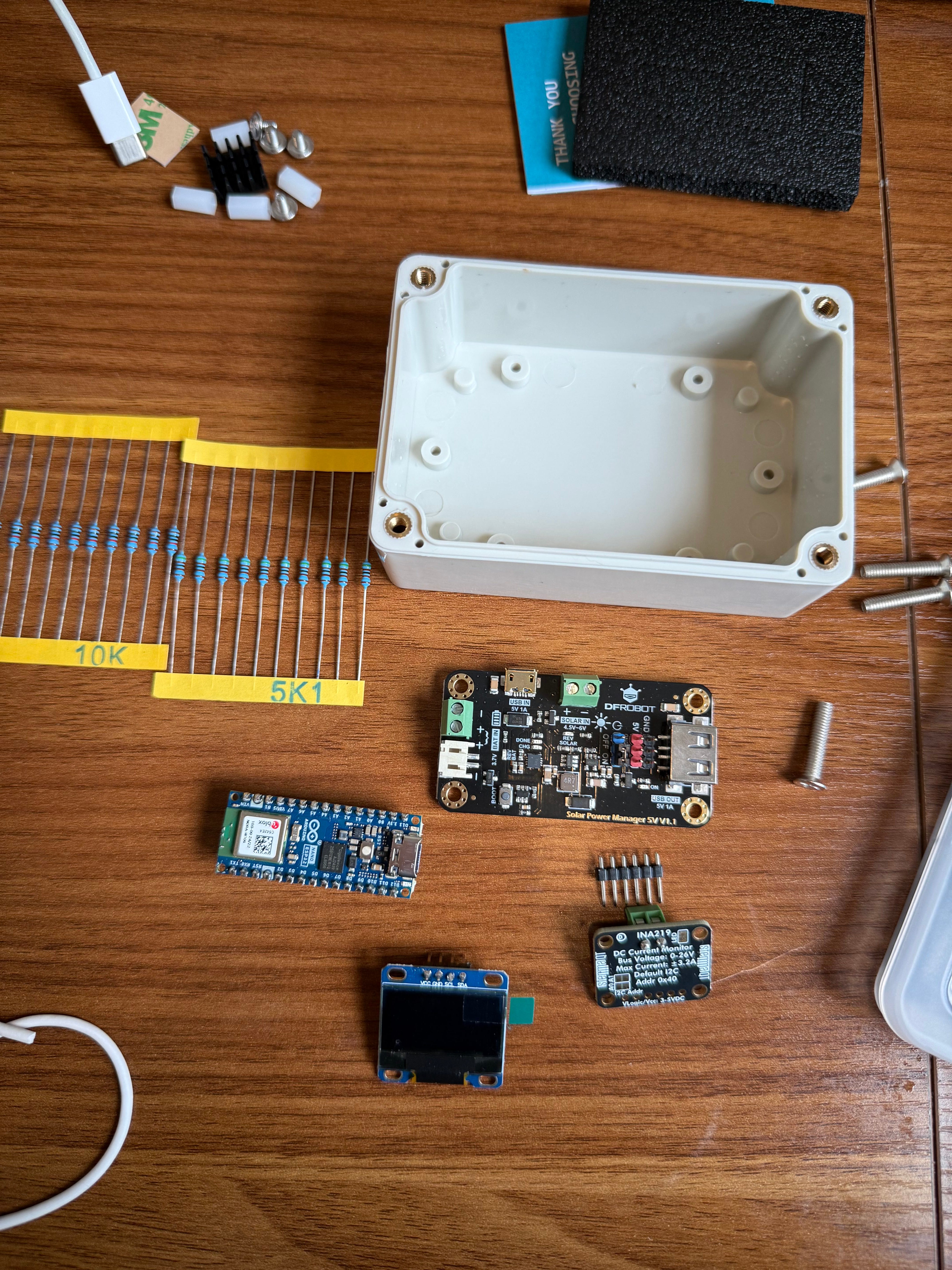
The ESP32 connects to my laptop via USB-C, and I downloaded the Arduino IDE on my computer to write the code to display my current on the OLED display.
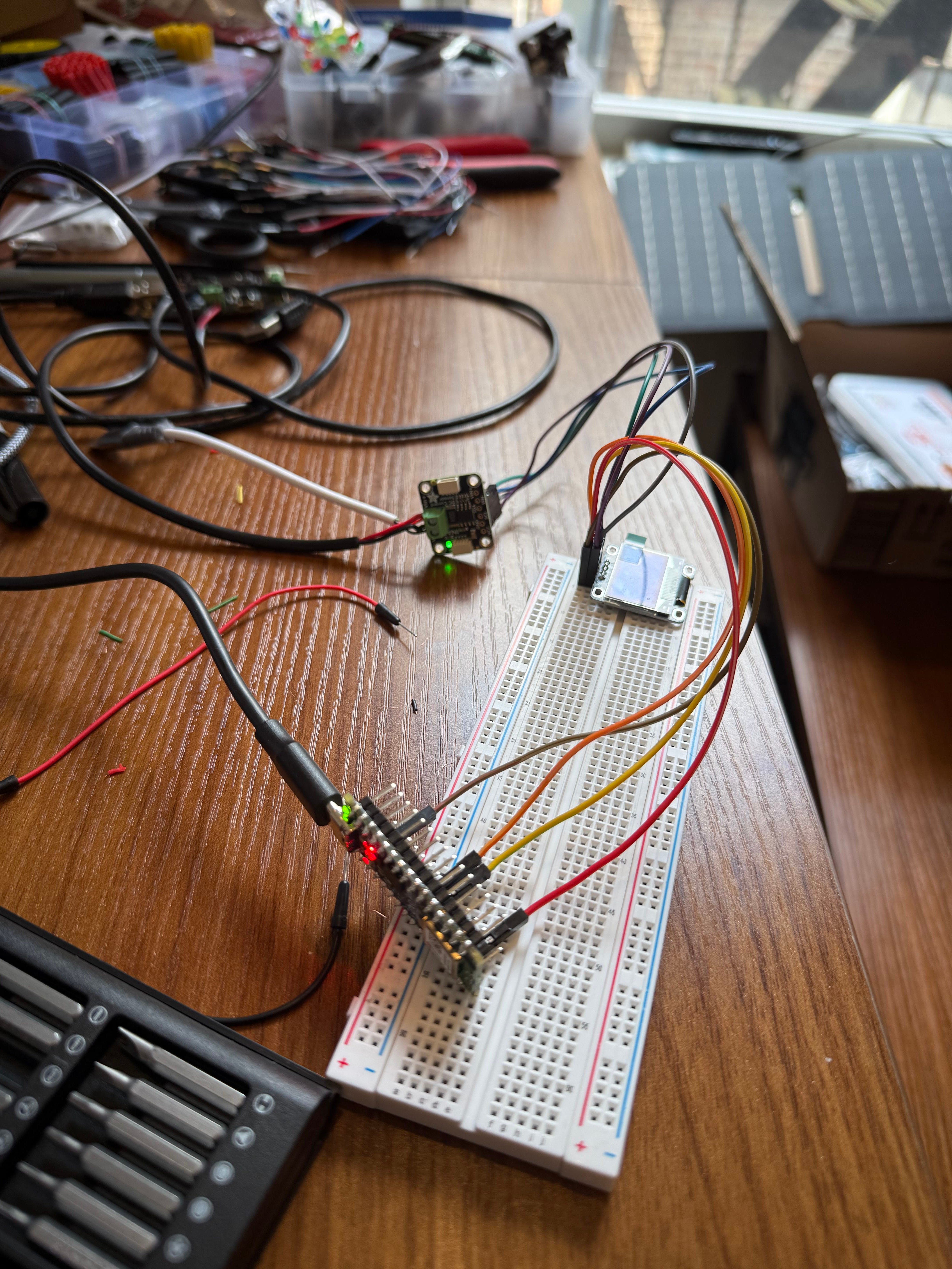
To first test that my system worked, I used a breadboard to connect these items. A breadboard (the white block shown below) is a device often used to prototype electronic circuits because it allows for temporary connections between components without soldering (melting iron to create junctions and permanent connections between components). The connections between the cables that are inserted run within the breadboard. These were the connections from ESP32 to OLED + INA219:
ESP32 3.3V → INA219 VCC
ESP32 GND → INA219 GND
ESP32 A4 → INA219 SDA
ESP32 A5 → INA219 SCL
Here you can see that I’ve connected my ESP32 with Dupont cables to my OLED display and the current sensor:
I (entirely with Claude’s help) was able to write some code which would display the following fields on my OLED:
Bus voltage: This is the voltage on the input side of the sensor from my solar controller. It shows how much voltage the controller is providing, and should read close to 5V when all is working properly.
Load voltage: This is the voltage on the output side of the sensor (going into the device being charged). This should be pretty close to the bus voltage, since the current is just passing through the sensor and going into the power bank.
Current (measured in mA): This represents how much electrical flow is happening, and has positive and negative values. If it’s positive, that means the solar panel is charging my power bank, but if it’s negative, the power bank is draining.
Power (measured in mW): This represents the total energy being transferred per second. The higher the values, the better the solar charging conditions.
Status: The two outputs are “NO CHARGE” or “CHARGING” to indicate if my power bank is being charged by solar power.
Below is a screenshot of some of the code:

putting it all together
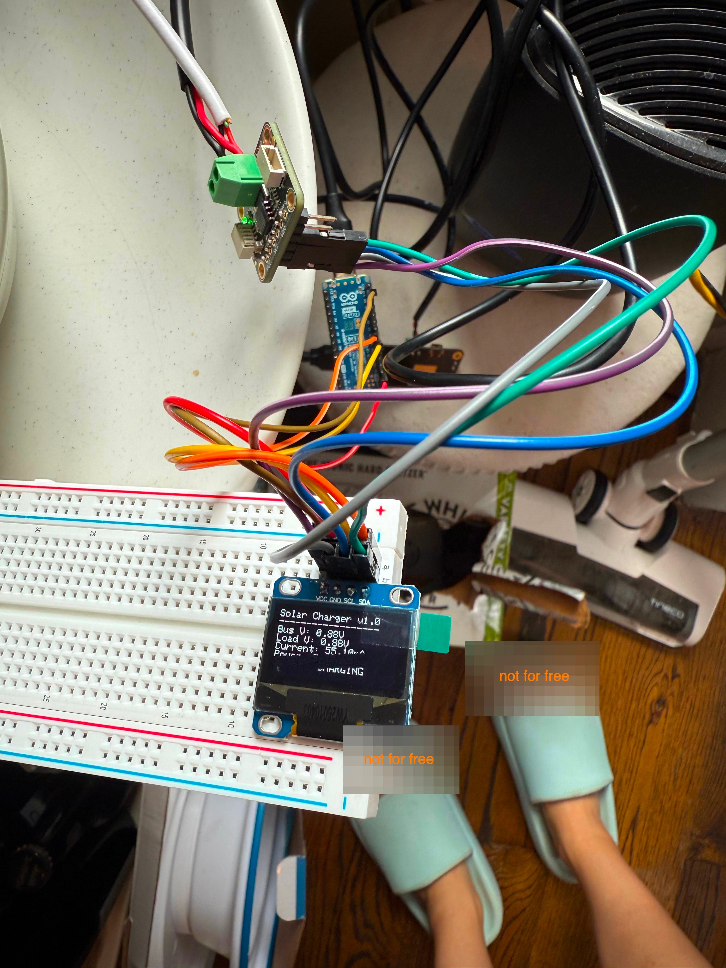
After configuring my ESP32 + the OLED display + the sensor + the controller, I connected everything to the solar panel + battery pack that I intend to charge. By this point, it was 4pm and the sun wasn’t super bright, and I was testing this in my apartment. As a result, there wasn’t sufficient sunlight to charge my battery pack (as you can see below, the Bus Voltage + Load Voltage (Bus V + Load V) were abysmally low at 0.88V - not even 1/5th what it needed to be.)
Despite that disappointment, it appears to work! I just need to confirm that it does under direct sunlight, for a longer period of time.
next steps: soldering + building v1
The breadboard pictured above was just meant to test the connections - it does not fit inside my junction box, and I will need to create a more permanent setup for my connections.
So, I have assembled a soldering kit, a wire stripper, a bigger junction box, a perfboard (to replace the breadboard), and plenty of spare USB cords to cut up and create the connections.
I’m super excited to learn how to solder and put it all together. Work is super busy this week, but hopefully I can share an update by the end of the week with how that goes before my trip next week.
Thanks for following along! If you’re working on similar things or curious about this project, please reach out, as I’d love to connect! :) Again, I barely know what I’m doing here, so any and all feedback is helpful and welcome.
LETSGOOO
first recorded instance of vibe charging